Engineering Context
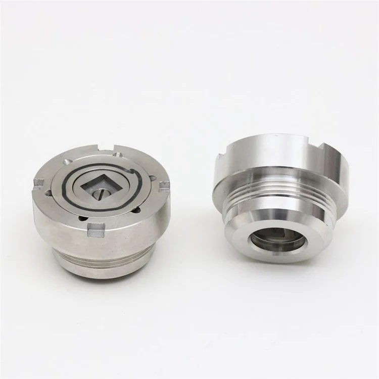
Drilling is more than making an opening in a metal component. Hole diameter, true position, perpendicularity, entry burrs and the condition at the bottom of a blind hole can all affect assembly. The first step is to read the drawing and distinguish through holes, blind holes, tapped holes and precision locating holes.
Process and Design Choices
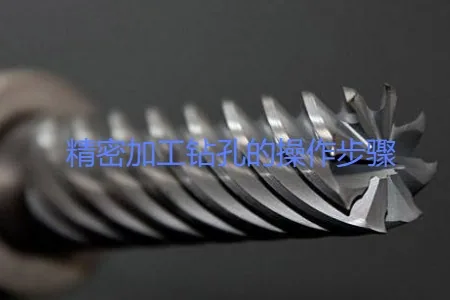
Process planning starts with the workpiece material, hole size, depth-to-diameter ratio and available machine rigidity. A repeatable datum and secure fixture come before cutting parameters. Drill selection, spindle speed, feed, coolant delivery and chip evacuation are then matched to the application. Critical bores may need reaming or boring after drilling rather than relying on the drill alone.
Common Problems and Risks
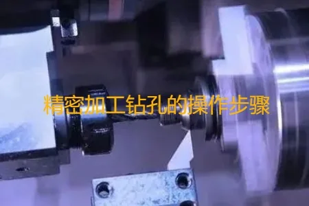
Runout can enlarge a hole; excessive tool overhang can shift its position; poor chip evacuation can damage the wall. Tough alloys and deep holes also introduce heat and chip-control problems. A first-off inspection after setup or tool changes helps detect drift before it reaches a production batch.
What to Specify and Check
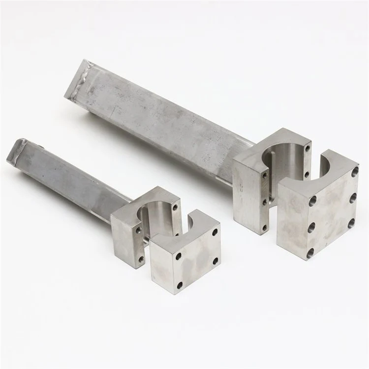
A usable RFQ drawing should state diameter tolerance, depth, true-position requirement, datum scheme, thread specification and burr acceptance. Go/no-go pins, bore gauges and CMM inspection serve different purposes. Identify functional locating holes separately so the supplier can plan the right final operation and inspection frequency.
Illustrative Application (Not a Customer Case)
Consider a hydraulic manifold containing both locating bores and oil passages. Locating bores need a controlled datum and fit, while intersecting oil passages place greater emphasis on burr removal and internal cleanliness. Equal hole diameters do not make the acceptance criteria identical.
Practical FAQ
FAQ: Why can assembly fail when a drilled diameter passes inspection? Check true position, perpendicularity, burrs and the relationship to mating datums. Diameter alone may not control the functional fit.
Information for a Manufacturing Review
For a drawing-based custom component, provide the controlled 2D or 3D drawing, material specification, expected quantity, critical features and applicable inspection requirements. Final manufacturing and acceptance criteria should be agreed in the project documentation.