In CNC machine tools, the self-locking cannot be achieved because of the reversibility of the movement of the ball screw nut pair. When the machine does not use or suddenly loses power, for the vertical drive (gravity axis, such as the Z axis of the vertical machining center, the Y axis of the horizontal machining center) or horizontally placed high-speed large inertia drive, in order to prevent the lead screw due to gravity of the spindle box When the spindle box slides down, it must be equipped with a brake device. Failure to do so can result in machine damage or scrapping of parts.
Traditional CNC machine tools use weight balance (for vertical machine tools) or hydraulic balance (for horizontal machines) (counterbalance) to reduce the forward and reverse load difference of the motor while reducing the axial gravity on the screw. However, many domestic and foreign machine tool manufacturers today have to remove the hydraulic balance device to simplify the structure of the machine tool and use the built-in brake of the servo motor to lock the rotation of the ball screw.
1 How the built-in brake works
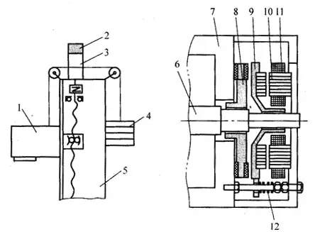
Fig. 1 Electromagnetic brake holding brake 1 - Headstock 2 - Electromagnetic brake 3 - Servomotor 4 - Counterweight 5 - Post 6 - Rotor 7 - Motor Stator housing 8 - Brake disc 9 - Armature 10 - Magnetic core 11 - Brake coil 12-Spring As shown in Figure 1, the brake disc and the rotor are splined, rotate with the rotor, and move axially. When the motor is in normal operation, the electromagnetic brake coil is energized, the armature overcomes the spring force and the iron core under the action of the electromagnetic force, the brake disc is released, the motor is in a relaxed state; when the brake is applied, the electromagnetic brake coil is de-energized, and the electromagnetic force is Disappearing, the armature moves axially under the action of the spring and pushes the brake disc, so that the brake disc is pressed tightly between the armature and the motor end cap. Thus, the motor rotor is locked by the friction torque generated by the brake disc. , resulting in braking effect.
Figure 2 shows the FANUC servo motor with brake. The first socket on the left is the power supply for the brake. When the motor is energized, the brake is released; conversely, the motor is de-energized and the brake is held tight against the motor shaft.
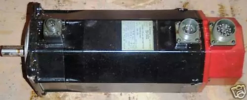
Fig. 2 Servomotor with brake Note: The built-in brake of the motor is used to prevent the vertical axis from falling when the servo is powered off. It only works during a tight stop or sudden power failure. It cannot be used for normal (motor is in excitation state) to decelerate the brake, otherwise the motor Will overheat.
2 Brake power supply configuration The built-in brake of the servo motor is essentially a DC electromagnet that is released on power-up. The brake of FANUC βis series servo motor uses DC 24V power supply and is obtained through transformer and diode full-wave rectifier, as shown in Fig.3. For full-wave rectification, considering the voltage drop in the rectifier or cable, the secondary voltage of the transformer should be about 29 V AC (Urms), so adjust the position of the primary input tap, such as 100-110-120VAC or 200-220-240VAC. Full-wave rectification output voltage rms value of Uorms = 0.9Urms, and finally check the brake power supply voltage fluctuations within ± 10%.
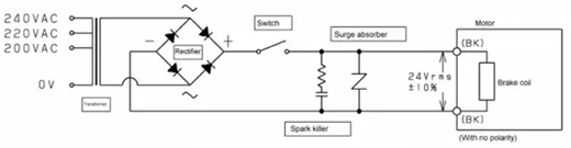
Figure 3 Brake DC 24V power supply circuit The surge voltage generated when the brake coil is de-energized will shorten the life of the relay contact, so select a contact with sufficient capacity and always use a spark killer and a surge absorber (surge absorber) to protect the contacts.
During the design process, do not share with the 24V power supply used by CNC and SV. Otherwise, the CNC or SV amplifier will malfunction. This is because it is better to keep the CNC power supply for a longer period of time when the power is turned off, and for the brake, the quicker the better the power-off reaction is, so that it can be braked quickly. Therefore, the filter capacitor is not included in Figure 2, and it cannot be too large, if any. However, the brake power supply can share 24V with other relays or coils. Pay attention to the power supply capacity.
FANUC's early servo motor built-in brakes were not necessarily powered by 24 VDC. See the video below.
The motor model in the video is FANUC 10S. When the brake socket is not connected to the power supply, the rotation shaft does not move. When the energized voltage and current reach a certain value, the shaft can rotate.
3 Brake power-on and power-off sequence There are two ways to brake and lock the vertical axis: When the power is on, the servo motor is excited and locked, and when the power is off, the mechanical brake disk is locked. When there is a change between the power and the no-power state (the CNC power is lost during a tight stop, power failure, or motor excitation), the vertical axis will fall if the two brake action times are not well connected. Therefore, the timing problem of the brake (vertical axis) release and servo ON (motor excitation) must be considered. In the same way, the timing of brake activation (ie brake) and servo OFF must be considered. As shown in Figure 4,5.
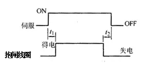
Figure 4 Servo and brake operation timing diagram
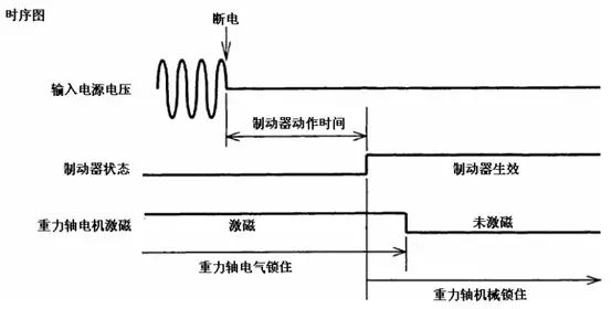
Figure 5 Servo and brake operation timing diagram when the power is off Servo motor to start operation, the first servo drive (servo ON), so that the motor to establish a holding torque, delay a period of time t1, the electromagnetic brake coil energized, brake When the brake is released, the servo motor begins to operate. When the brake is applied, the electromagnetic brake coil is de-energized. The brake generates a braking torque. To ensure the reliability of the brake, the servo ON continues to be turned on, so that the servo motor continues to have a holding torque. Servo ON is Delay after a period of time t2 disappears. That is, the brake operates as soon as possible after the power failure is detected, and the brake is used to hold the motor shaft before the excitation of the motor is turned off (as shown in FIG. 4 ).
4 Measures to reduce the amount of vertical axis drop (1) The brake must work immediately to minimize the amount of drop.
In order for the brake to work quickly, the switches and relays that control the opening and closing of the brake must be designed on the DC side. If installed on the AC side (eg, between the transformer secondary and the rectifier), the brake operation is delayed because of the time required for the current to return to the rectifier diode.
(2) Switches and relays that control the opening and closing of the brake must act quickly in the event of sudden power failure to reduce the amount of drop.
For this purpose, a relay with a short operation time (for example, 10ms) is selected, and a drive power source for the relay is provided from the main power supply circuit (high voltage, such as 200V), as shown in FIG. 6 .
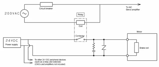
Fig. 6 Relay coil power supply for controlling the on/off of the brake (3) Keeping the holding time of the CNC and amplifier control power supply (DC24V) This time should be longer than the brake operating time. When necessary (such as a large control power load), the UPS can be used to extend the NC and amplifier control power maintenance time. The purpose of the ON/OFF circuit A selected by the CNC when it is powered on is to maintain the maintenance time of DC24V when the power is off, as shown in FIG. 7 .
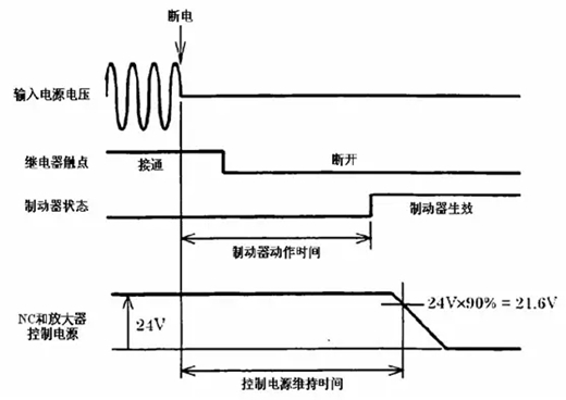
Fig. 7 Relationship between the power supply and brake operating time of the CNC (4) "Brake function" of the servo software
The drop of the axis due to the delay of the brake operation can be avoided by adjusting the "brake function" parameter of the FANUC servo software. This function allows the motor to continue to energize for a set time before the brake is actuated, as shown in Figure 8.
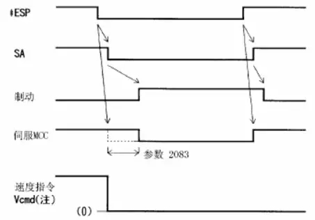
Figure 8 "Brake Function" in Servo Software
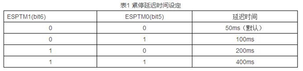
It is possible to delay the control of the MCC power-off time within a certain range. In addition, it is also possible to delay the action of the tight stop. Set the general brake action time to t1, select the MCC delay power-off time t2 is greater than t1, emergency stop action time t3, t3> t2, you can achieve the purpose of controlling the headstock down. For example, select t1=50~100ms, t2=200ms, and t3=400ms.
Set as follows:
P2005#6=1, the brake function is valid. P2083 sets the delay time (ms)t2. It is generally set at 200 or so. Assume that the mechanical clamp time t1 is about 50-100ms, depending on the amount of mechanical gravity.
P2210 bits 6 and 5, set the stop delay time t3, which is longer than the time set in 2083, as shown in Table 1.
(5) The FANUC 0i Mate-D's new design has a brake process inside the FANUC 0i Mate-D servo drive unit. The CX38 terminal is connected to 3-phase AC 200V, and the CX36 terminal is connected in series to the tight stop control circuit.
(6) Lifting function of the gravity axis during tight stop Even if the gravitational shaft fall prevention measures are effectively taken, due to the mechanical gap of the brake, the gravity axis will still drop a certain distance (20 μm at 10 mm/rev), and this can be taken as “tight When the stoppage occurs, the gravity axis lift function will lift the gravity axis a certain distance and then tighten the shaft to offset the influence of the brake clearance.
For example, Mori Seiki Co., Ltd. designed the “prevent the Z axis from falling” function to avoid damage to high-priced molds due to the fall of the gravity axis during a sudden power failure. The spindle is slightly lifted during power failure to avoid damage to the workpiece. As shown in Figure 9.
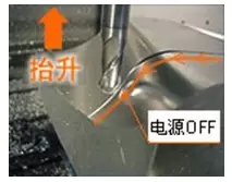
Fig. 9 Mori Seiki's prevention of Z-axis drop function 5 Design example The vertical control system of VMC 750 brake is shown in Fig. 10. Among them, KA11 is a power-off detection relay, which is installed on the DC side of the brake control circuit and can detect the power failure. When the time brake is actuated quickly, the relay is driven by the input power AC110V to reduce the amount of drop. KA12 is the brake release relay. The PMC turns ON when the servo ready signal (SA) is "1".
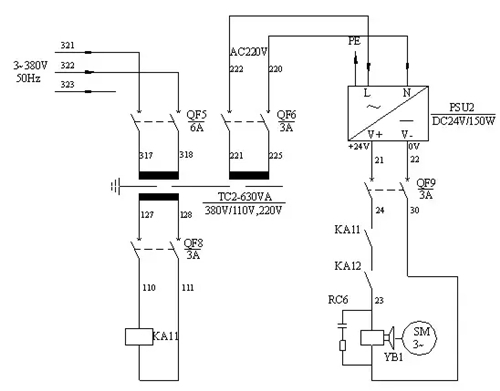
Figure 10 VMC 750 brake control loop 6 Conclusion In fact, many CNC machine tools are set to return to the machine's zero position, which is to eliminate the vertical axis drop caused by power failure. Experienced operators also perform reference point operations after the machine has been stopped.
Design should consider reducing the production cost, but some CNC machine manufacturers blindly in order to save costs, the design of the electrical control system can only guarantee the realization of the most basic actions, ignoring some of the security protection design. This is not desirable and should be strictly followed.


 September 10, 2023


